
In the design of pressure vessels, particularly for nozzle-to-shell junctions, accurate assessment of local stresses under internal pressure and external loads is paramount. These regions are prone to stress concentration and fatigue, making their analysis critical. Engineers routinely use established design bulletins such as WRC 537 or WRC 297 to evaluate the stress intensification effects caused by external piping loads or internal operating pressures on nozzles.
One of the key parameters used in these calculations is the nozzle neck thickness. However, engineers are often split between two choices: should the nominal wall thickness of the pipe be used? Or should the minimum pipe thickness, accounting for manufacturing tolerances, be considered?
While the difference may appear small — typically around 12.5% — this decision has direct consequences on stress results, compliance with the ASME code, and ultimately the safety and reliability of the vessel. This article examines the issue from theoretical, practical, and code-based perspectives, with specific reference to ASME BPVC Section VIII, Division 2 (2023 Edition), and the implications for WRC-based stress evaluation.
Understanding Hoop Stress and Thickness Sensitivity
Stress in pressure vessels is inversely proportional to thickness. For a cylindrical shell or pipe under internal pressure, the hoop stress (σh) is defined as:
- P = internal pressure
- R = the mean radius of the nozzle neck or shell
- t = wall thickness
From this equation, it is evident that a reduction in wall thickness increases stress proportionally. In localized analysis such as nozzle-to-shell intersections, even small variations in thickness can lead to elevated stress concentrations, potentially exceeding allowable limits, especially under combined loading conditions (pressure + piping loads + thermal expansion).
Visualizing the Impact: Uniform vs. Asymmetric Thickness
Consider a pipe with the same outer diameter but varying thickness across the cross-section:
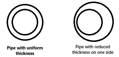
- Left side of diagram: in the first scenario, the wall thickness is uniform. The stress distribution is symmetrical and predictable.
- Right side of diagram: in the second scenario, the wall is thinner on one side and thicker on the other. Even though the average cross-sectional area may be similar, the thin side experiences significantly higher hoop and local stresses due to reduced thickness.
- This reinforces the argument that nominal wall thickness does not represent the weakest point of the component — design calculations must reflect the minimum thickness at any location around the circumference.
What ASME BPVC Section VIII-2 (2023) Says
ASME BPVC provides guidance and mandatory requirements regarding thickness usage in both design by rule and design by analysis. Two critical references from the 2023 Edition clarify how thickness must be interpreted for analysis.
1. Paragraph 3.2.10.2 — Pipe and Tube
This clause directly supports the principle that design must be based on minimum metal thickness. In other words, even though the nominal wall may be 12.7 mm, the pressure design and analysis should be based on the minimum actual thickness after accounting for undertolerance — typically 12.5% for seamless and welded pipe, unless otherwise stated in the material specification.

2. Paragraph 4.5.4 — Nozzle Neck Minimum Thickness Requirements
This section outlines how the minimum required nozzle neck thickness is to be calculated based on internal/external pressure and supplemented by external loads:
4.5.4.2 applies similar provisions to access and inspection openings.
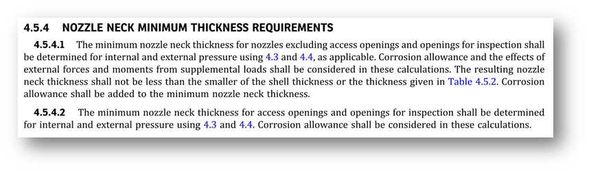
The intent is clear: the minimum wall thickness — after considering manufacturing tolerance and corrosion allowance — forms the basis for compliance. Any analysis, whether elastic stress analysis or WRC-based local assessment, must begin with the most conservative value: the least thickness the component will have in service.
WRC 537/297: Role in Local Stress Analysis
WRC 537 and WRC 297 are empirical methods derived from finite element results and test data. They are widely used for estimating stresses at nozzle junctions when subjected to loads such as:
- Axial force (tension or compression)
- Bending moment (in-plane and out-of-plane)
- Internal or external pressure
One of the main inputs in WRC methods is the nozzle neck thickness (tn). The calculated stresses (primary and secondary) are directly affected by this value, since it influences the local flexibility and stress indices (SIFs).
If the analysis is performed using the nominal thickness (say 10 mm), the resulting stresses will be artificially lower compared to those calculated with the minimum expected thickness (say 8.75 mm). This can result in underestimation of local stresses and misclassification of stress categories (e.g., primary vs. secondary), and under certain conditions, may lead to unsafe designs.
Worked Example: Nominal vs. Minimum Thickness
Consider a standard SA-106 Grade B seamless pipe (NPS 12-inch Sch. XS) used as a nozzle, with a nominal thickness of 12.7 mm and a manufacturing tolerance of −12.5%:
In WRC 537 / WRC 297 / FEA analysis:
- If nominal thickness is used, calculated membrane and bending stresses may fall within allowable limits.
- If minimum thickness is used, stresses increase — and might require design changes (e.g., thicker nozzle, pad reinforcement, or nozzle relocation).
Using minimum thickness from the outset ensures the design remains conservative and code compliant.
FEA Verification
To quantify the effect directly, two simple FEA hoop-stress models were run on the same pipe geometry — one with uniform wall thickness, one with an asymmetric wall (thicker on one side, thinner on the other) that averages to the same nominal thickness.
- Outside diameter, D = 323.90 mm
- Mean radius, R = 155.6 mm
- Internal pressure, P = 1 MPa
- Pipe length, L = 500 mm
Case 1 — Uniform Thickness
Case 2 — Asymmetric Thickness (tthick = 14.2875 mm, tthin = 11.1125 mm)
The uniform-thickness pipe shows a symmetric, predictable stress distribution centered around 12.25 MPa. The asymmetric pipe — same nominal average thickness — shows a peak hoop stress of 14.0 MPa on the thin side, about 14% higher than the uniform case, concentrated exactly where the minimum thickness occurs.
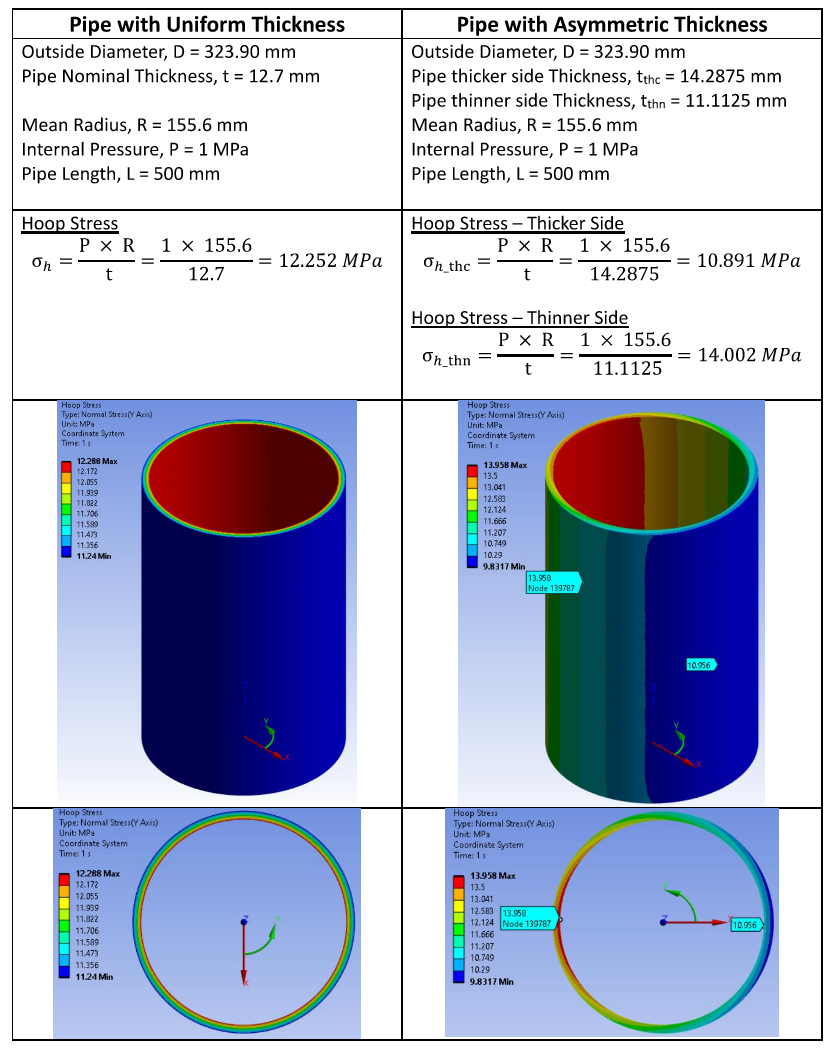
The FEA contour plots confirm the hand calculation almost exactly (13.958 MPa modeled vs. 14.002 MPa calculated) and make the physical point visually unambiguous: stress concentrates at the thinnest point on the circumference, not at the nominal average. An analysis run purely on nominal thickness would never see this peak at all.
Corrosion Allowance: Further Reducing Effective Thickness
ASME further requires that corrosion allowance be considered in addition to undertolerance. For example, if a 1.6 mm corrosion allowance is specified:
This is the thickness to be used in elastic finite element analysis or WRC calculations — not the nominal 12.7 mm. Failure to use this reduced value compromises the credibility and conservatism of the analysis.
⚠ Common Mistake
Using nominal thickness directly in a WRC 537/297 or FEA nozzle stress evaluation is one of the most common — and most consequential — shortcuts in local stress analysis. It doesn't just under-report the stress by a small margin; it can silently misclassify a governing stress category (primary vs. secondary) and pass a design that would fail under the code-mandated minimum thickness.
Practical Takeaways
- Always refer to ASME VIII-2, paragraphs 3.2.10.2 and 4.5.4 when modeling nozzle or pipe components.
- Deduct manufacturing tolerance (commonly 12.5%) from nominal thickness before performing elastic stress analysis or using WRC bulletins.
- Add corrosion allowance to the required thickness when sizing components.
- For fatigue analysis or cyclic service, this conservative approach is even more critical.
- Document the assumption clearly in the design report — e.g., "Nominal t = 12.7 mm, Mill Tolerance = 12.5%, CA = 1.6 mm, Minimum t used in analysis = 9.5125 mm."
✓ Verified Against ASME BPVC.VIII.2-2023
All hoop stress values in this article were independently recalculated from the stated geometry and pressure — the uniform, thicker-side, and thinner-side hoop stresses, the minimum design thickness, and the corrosion-allowance-adjusted effective thickness all match the source FEA report exactly. The code references cited (3.2.10.2 and 4.5.4) are quoted directly from ASME BPVC Section VIII, Division 2, 2023 Edition.
Conclusion
The practice of using minimum wall thickness in nozzle stress analysis is not just a matter of engineering judgment — it is codified in ASME BPVC Section VIII, Division 2 (2023 Edition). Both paragraph 3.2.10.2 and section 4.5.4 make it clear that manufacturing tolerances must be accounted for in thickness selection for both design and analysis. Using nominal thickness in WRC-based analysis can lead to unconservative stress estimates and code non-compliance.
Designing conservatively, especially at critical junctions like nozzle connections, ensures long-term vessel integrity, regulatory compliance, and operational safety. When in doubt, choose the thinner path — it's the one ASME paved for safer engineering.
Need to Run a WRC 537/297 Nozzle Stress Check?
Explore this site's free ASME VIII Div.1 thickness calculator and structural analysis tools to size your nozzle and shell components before running a detailed local-stress evaluation.
Open the ASME VIII Div.1 Thickness Calculator →